This page contains images and wiring information for connectors commonly
used on micro models.
There is a lot of confusion and differences of opinion about which part of a
mating connector pair is the socket and which is the plug.
Micron uses the shape of the plastic parts to define plug and socket
- the plug fits into a matching hole in the socket.
The image below of servo connectors contains plugs.
Servo/ESC Conn (top)
Micro R/C gear uses a variety of connector types for servo and ESC.
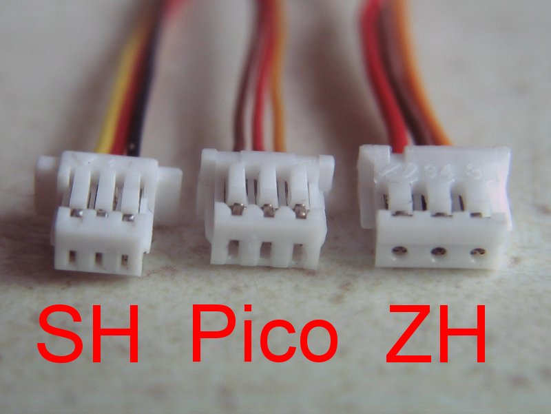
The 3 most common are:
|
- JST-SH:
- 1mm pin spacing
wires L->R: signal, positive, negative
- Molex Picoblade:
- 1.25mm pin spacing
wires L->R: negative, positive, signal
- JST-ZH:
- 1.5mm pin spacing
wires L->R: positive, negative, signal
TAKE CARE: although the convention is for negative on the centre pin, some
equipment may have different wiring.
|
The plugs for these connectors are all crimp type and, ideally, the special tool
is used to form the crimps. This, however, is very expensive (> £300);
cheaper tools are available for approx £40 (search on ebay for 'universal mini micro crimping tool pa-09').
If you don't have the real or cheaper crimp tool, then (with care)
snipe nosed serrated edge pliers may be used to squeeze the crimp
over the wire. Strip 1-2mm of insulation from the wire and insert into
the crimp - I use tweezers to hold in place with one hand while folding the
tabs of the crimp using the pliers in the other hand. Fold the insulation
grip tabs first followed by the wire grip tabs. The insulation tabs should
be squeezed just tight enough to hold the wire, any tighter and you may
break through the insulation. The wire grip tabs should be squeezed as tight
as you can.
Do not attempt to solder the crimp as the
small size encourages solder to wick into
the parts that need to flex
'UM' Single Cell LiPo (top)
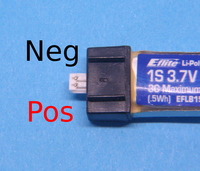
Most single cell LiPo use a 2 pin Molex PicoBlade
plug - the 'UM' Ultra Micro connector.
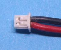
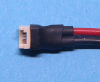
Power leads for receivers and ESC are fitted with a matching
socket - using either crimped or solder terminals.
The connector is polarised using a cutout in the socket which accepts
the 'bumps' on the plug used to retain the metal crimps.
The wiring convention for plug and socket is show below:
'UM' LiPo |
'UM' Plug |
'UM' Solder Pin Socket |
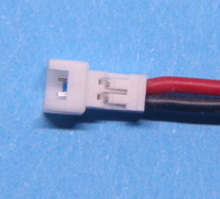
'UM' Crimp Socket |
JST-PH Connectors (top)
The JST-PH is commonly used on small 1S and 2S LiPo.
Polarisation uses a 'fence' on the plug which fits into a slot on the socket;
the plug fence is on the opposite side to the barbs which hold the
metal crimps in place.
2 Pin
The 2 pin connector is used for high current 1S LiPo where the discharge
current is too much for a 'UM' connector, which is specified to 1A
(although frequently used up to 2A).
Note: the JST-PH 2 pin pos/neg connections on LiPo sold into the
modelling market is opposite to that used in the robotics and electronics
maker markets.
The images below are of connectors for modelling 1S LiPo.
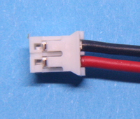
2 Pin Plug |
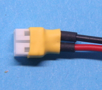
2 Pin Socket |
3 Pin
The 3 pin connector is used on 2S LiPo to eliminate the need for separate wires
and connectors for discharge and charge balancing.
Note that the positive and negative wires are swapped when compared
with the 2 pin plug. The centre wire is connected to the centre tap of the
2 LiPo cells.
Receivers and ESC do not require a connection to the centre pin.
An adapter is available
for charging these 2S LiPo from a charger with the common JST-XH balance socket.
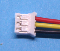
3 Pin Plug |
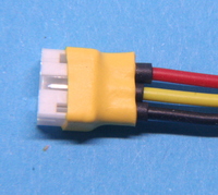
3 Pin Socket |
JST-RCY Connectors (top)
This connector goes by several names, often called just "JST". The correct
name is JST-RCY;
it is a compact 2 pin 2.5mm pitch wire-to-wire connector
commonly used for low-current power connections.
JST rate this up to 3A but modellers often take it up to 5A.
The plug is often found on small LiPo batteries and the socket (receptacle)
on speed controllers. The convention for location of positive and negative
wires is shown below.
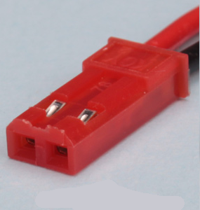
Plug |
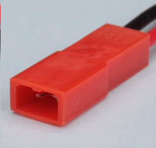
Socket |
Molex 2mm Pitch Connectors (top)
Molex 2mm connectors are used for small LiPo,
they are smaller than JST-PH and
the insert/disconnect force is lower which makes them suitable for use
in small models / restricted space installations.
3, 4 and 5 pin versions of this connector can be used for balance connections
where a JST-XH would take up too much space.
Unfortunately, there is no manufacturer consistency in the way that the
negative and positive wires are inserted into the shell.
The Micron convention is that negative is at position 1 as shown
in the images of the 2 pin connector below;
please contact us
if you need your LiPo or Molex 2mm leads wired with pin 1 positive.
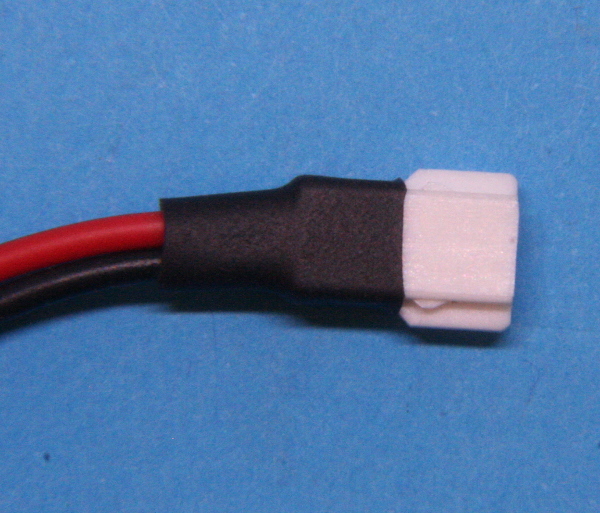
2 Pin Plug |
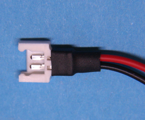
2 Pin Socket |
The small retention lugs at the side of the plug can be removed
with a scalpel to
make the insert/disconnect force even lower; these are the tiny bumps in the
white plastic seen near the black heatshrink.
DO NOT remove the larger tabs as this will defeat the polarisation protection.
Removal of the retention lugs is recommended when the
connector is used in a restricted space - e.g. inside a loco body.
